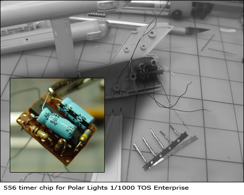
Polar Lights 1/1000 TOS Enterprise 
Warning
Just to let you know, I don’t know what I’m doing. I never know what I’m doing; I’m just winging it. I regularly blow multimeters when trying to check resistance on a live circuit. I know what Ohm’s Law is but I’ve never actually used it.
By Jennifer Petkus
Currently, I’m working on a little Polar Lights 1/1000 scale TOS Enterprise. It’s a snap together kit and has a few issues because of that, but it’s very cheap and with a lot of puttying and sanding, builds up into a nice kit (or so I’m told, because this is my first).
But I won’t talk about the build because there are may fine write-ups on Starship Modeler. Instead, I thought people might be interested in how I decided to light the kit. Consider this a little payback to all the great tutorials I found on the web. I just wanted to collect all the these techniques in one place.
(By the way, I decided not the light the windows. This model was just practice for the big refit so I decided to just use the window decals in the kit. I also decided to ignore all the other little lights, like the lights above the shuttle bay.)

Buy this kit at:
Starship Modeler
Colpar Hobbies
Most people choose to light this kit by running wires into the model through a brass pole, replacing the stand that comes with the kit (a good solution), or by using a mini-plug that exposes the wiring. But I wanted to use the supplied stand and run the wires through it.
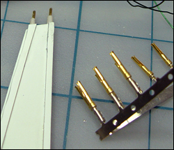
I thought it might be possible to use the plastic pins of the stand itself. I still had the gold pins I used to make custom RS-232 computer cables back in the old days before USB cables (they’re still used in things like VGA cables). The male pins are smaller in diameter than the plastic pins of the stand and with a pin vise, I carefully drilled into the stand.
I think you can find these pins at Digi-Key.com by clicking this link. I did a search for connectors / contacts / pins / sockets and I believe the part number for these things is DF11. These are called crimping connectors, but you’ll also want to solder the wire.
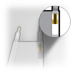
I also had to make a space inside the stand for the crimping connector. I’m sorry I didn’t take a photo of this, you can see the sheet styrene I used to cover my surgery on the stand, but this illustration might help. To run the wires to the connectors, I also had to dig a trench along the side of the stand. I plan to attach the stand to a wooden base and hide the power source inside.
Wire choice
I knew there wouldn’t be a lot of room in this model, so I chose armature winding wire to make all my connections, especially import for the wires that go to the nacelles. I picked up the wire at RadioShack. I believe the insulation is lacquer and you just scrape it off to make a soldered connection. (Because of the lacquer insulation, you might want to be careful with lacquer thinner. The insulation does seem to stand up to superglue. I used the green wire.)
You wouldn’t want to use this wire to carry a lot of current because it would overheat and set the model on fire, but I think it’s safe for this application. Again, always remember, I don’t know what I’m doing.